.:: Rail Gun ::.
Electromagnetic Linear Accelerator
LAST MODIFIED: 11-10-2021 | PAGE HITS: 2,851
Electromagnetic Linear Accelerator Experiment. Plasma armature. Rail guns are a good way to accelerate a mass using electric current. Basically when you run a current through a wire; the wire wants to become a streight line. If you have a closed circuit, the wire wants to become straight as well, but can only become round. When you run a current through the rails and the projectile in between, the circuit loop wants to become a circle, however the only variable that can change is the projectile displacement. This causes the projectile to accelerate. The major problem with rail guns is that the projectiles want to weld themselves to the rails, when high current is passed throguh. Some people suggest using graphite as the projectile armature. I will be using what is called, "plasma armature". The theory behind plasma armature is that a piece of metal explodes between the rails and the electric arc itself is doing the pushing, on the back of the projectile, therefor the projectile will be made of non-conductive material. The metalic vaporization will also add a kick start to the projectile. Hopefully the electric arc doesn't get ahead of the projectile itself.
RAILGUN SHOT #001
Velocity: >24 m/s
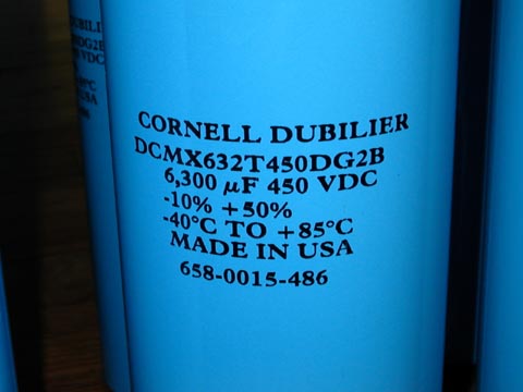
Capacitor Energy: 5 kJ
Projectile Energy: >0.26 J
Efficiency: >0.0052%
Comments: Because the projectile had an inelastic collision with the pendulum, only a lower bound reading could be made. The projectile bounced off of the pendulum taking with it the remaining momentum. The reason the projectile did not penetrate the apple is credited to the bellow freezing temperatures currently in New York. The apple hung overnight and froze solid before the test shot. The second shot will use a softer substance in order to achieve an inelastic collision.
Variables:
Mprojectile = 0.9 gm
Mpendulum = 213 gm
Lpendulum = 61 cm
Delta X = 2.5 cm
Delta Y = (61 cm) - (cos(sin-1((2.5 cm) / (61 cm))) * (61 cm)) = 0.053 cm
| Cammera 01 | Cammera 02 | |
| Frame 01 | 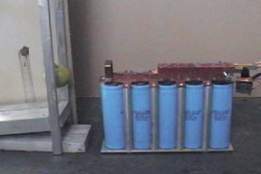 | 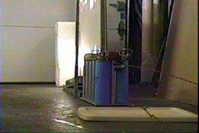 |
| Frame 02 | 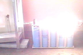 | 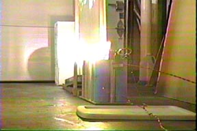 |
| Frame 03 | 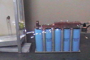 |  |
| Frame 04 |  |  |
Rail errosion from the plasma armature. Thanks to the plasma armature, the damage to the rails was very minimal and the rails are ready for the next shot.
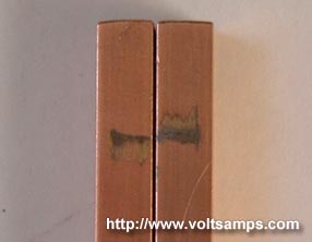
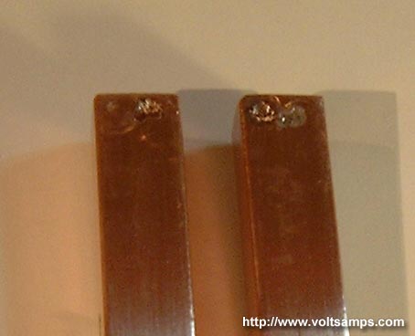
The spot weld marks from the rail clamps/terminals.
0.9 gram Delrin projectile.
RAILGUN SHOT #002
Velocity: 30 m/s
Capacitor Energy: 5 kJ
Projectile Energy: 1.04 J
Efficiency: 0.0208%
Comments: The second shot was very exciting because it would be the shot which told me exactly the railgun output. My ballistic pendulum setup now used a PVC container filled with gelatin which would guarantee an inelastic collision. The video shows the projectile lodging into the pendulum. You will also see a plastic spacer flying out of the projectile. Apparently, the spacer, which fills the gap behind the projectile, has compressed from the foil vaporization and shot out after the projectile. My mercury contactor which triggered shot 01 had internally failed and I was forced to manually trigger the railgun setup. Armed with welding goggles, ear plugs and a long stick I fired the railgun, which was a pretty frightening experience. After both videos were captured I was able to calculate a rough velocity, kinetic energy and efficiency using a ruler as a distance reference, a video editing program, and then an image editing program to make pixel-accurate distance measurements. Looking over the videos I noticed that there was much energy loss due to sparking and gasket leaks which isn’t a big deal on this railgun prototype, however tighter machining tolerances will improve efficiency by a huge factor.
Variables:
Mprojectile = 2.3 gm
Mpendulum = 304 gm
Lpendulum = 64 cm
Delta X = 5.7 cm
Delta Y = (64 cm) - (cos(sin-1((5.7 cm) / (64 cm))) * (64 cm)) = 0.258 cm
| Cammera 01 | Cammera 02 | |
| Frame 01 | 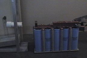 | 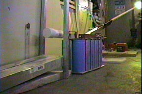 |
| Frame 02 | 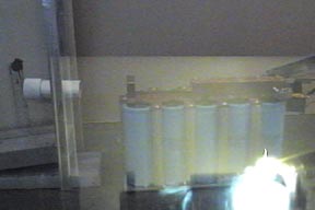 | 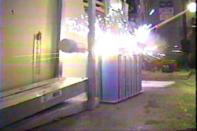 |
| Frame 03 | 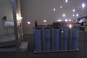 | 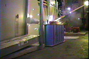 |
| Frame 04 | 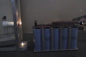 | 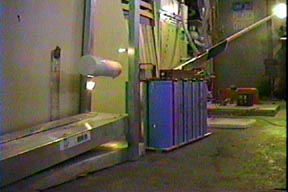 |
| Frame 05 | 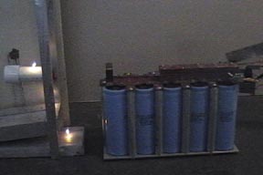 | 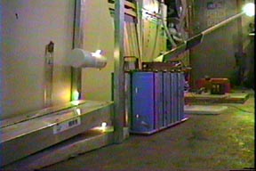 |
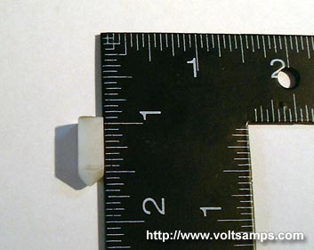
2.3 gram Delrin, steel core/tip projectile. This projectile is sharper than the previous and has a steel core for higher mass.
This is the top view of the rail enclosure after the shot. You can see signs of gasket leakage where the fiber glass enclosure is blackened.
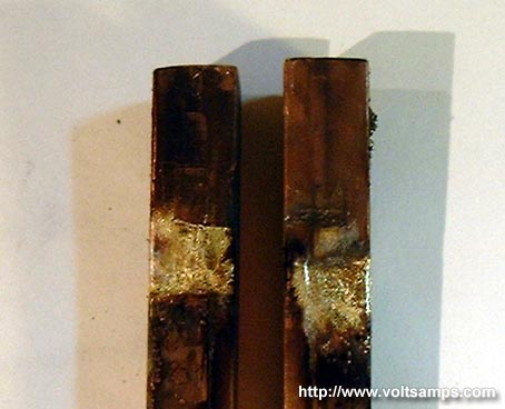
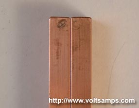
This is the damage done to the rails after the second shot. The rails have not yet been cleaned.
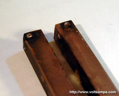
This is the damage done to the terminal clamp portion of the rails before the rails were cleaned.
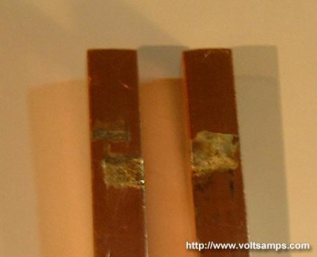
After cleaning the rails (not using steel wool or sand paper) you can see that the damage isn't at all as bad as it seemed, and the rails can be used over and over again. In a field version of this railgun the rails can be quickly and easily cleaned with some kind of steel wool and cloth material that can be pulled through the barrel.
This second shot shows that using graphite to improve terminal coupling with the rails wasn't a good idea as it caused more damage to the rails than the first shot. Graphite has somewhat of a high resistance and possibly vaporized during the current pulse.
MISC. PHOTOS

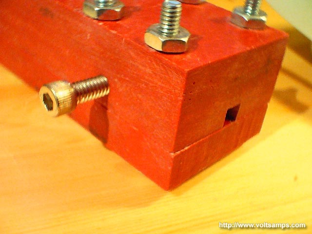
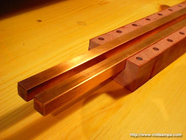
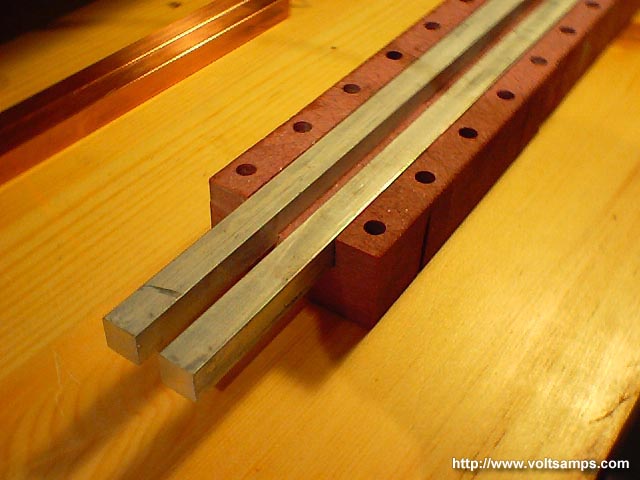
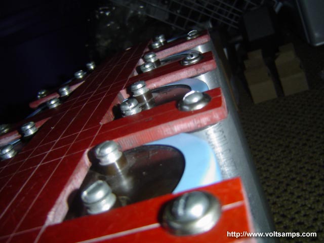
This was the original design of the rail gun.
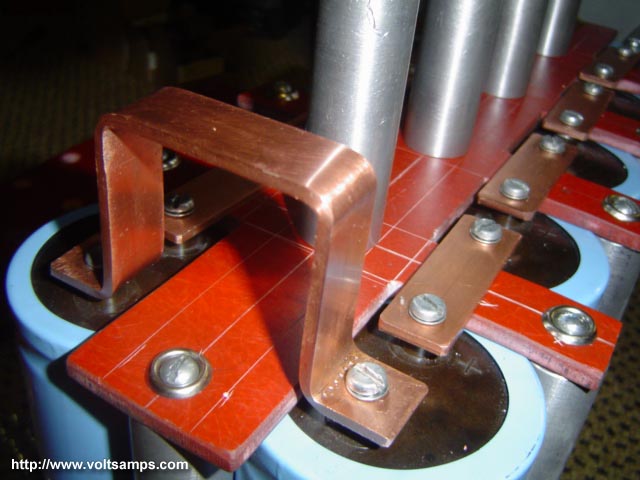
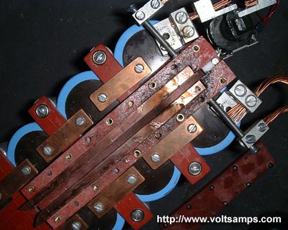
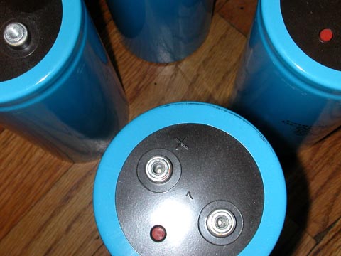
Original design. Close up for capacitor bus bars.
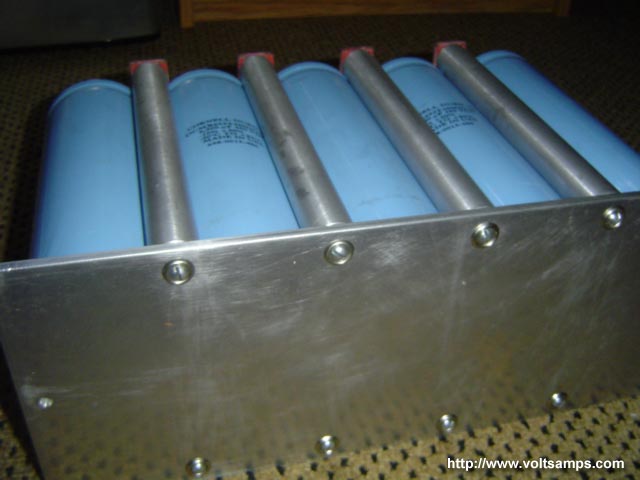
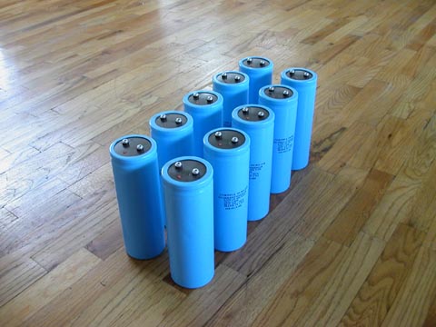
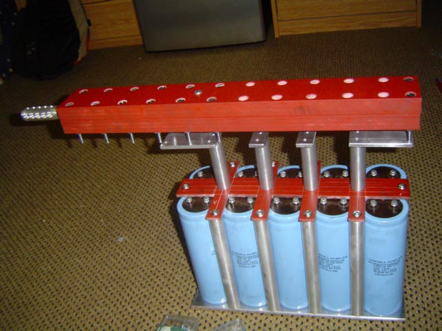
Bottom view of capacitor bank array.
Top view of the capacitor bank array.
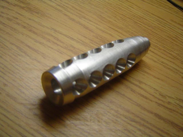
Muzzle flash supressor.
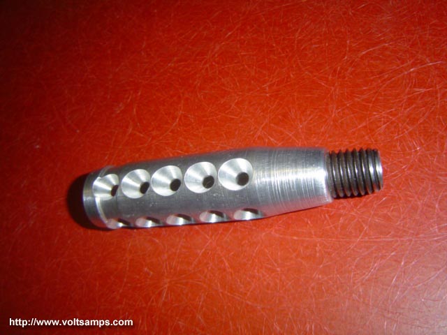
Muzzle flash supressor.
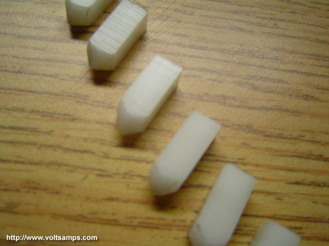
Delrin projectiles. Prior to adding sacrificial aluminum armature.